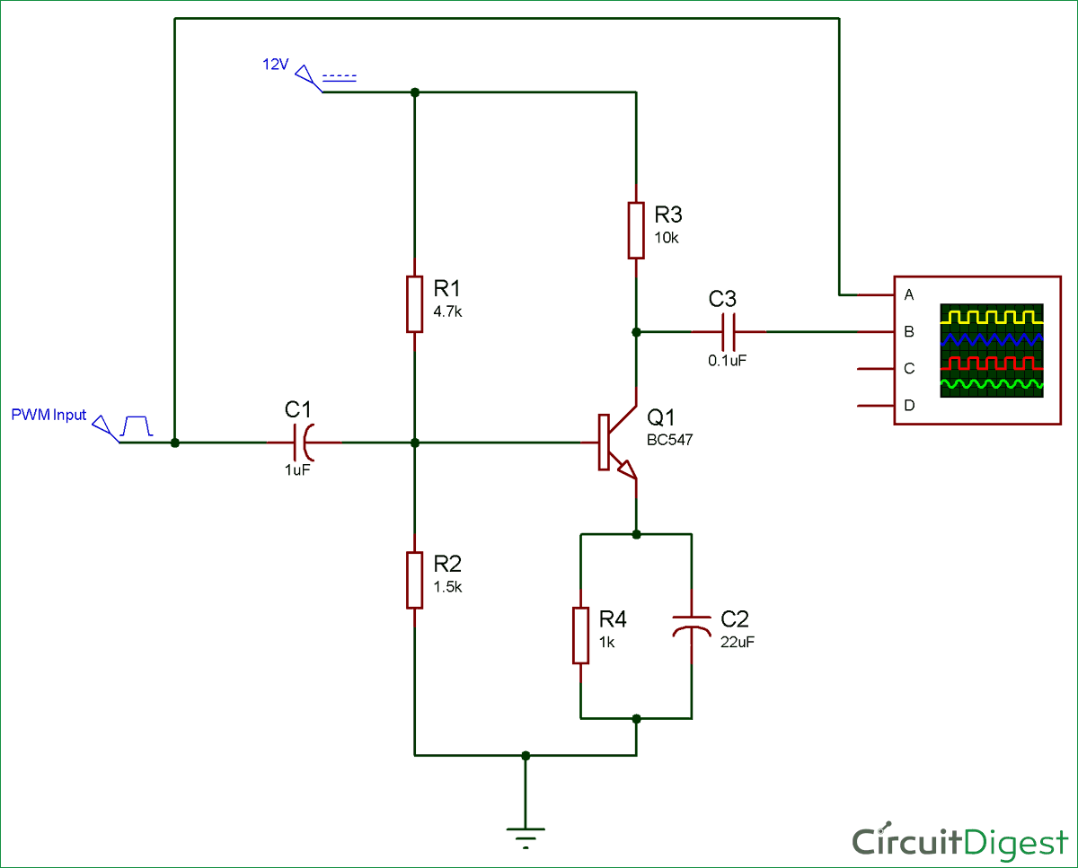
This changes the voltage drop across the load resistance because V CC is constant. The changes in the base current I B cause changes in the collector current I C. Amplifier using n-p-n transistor in common emitter configuration is shown below: Circuit Diagram: The emitter is common to both the input and output circuit.Therefore, the additional voltage drop in the input loop will be across resistor R B (= ΔI BR B) and across the input dynamic resistance of the transistor (= ΔI Br i). RESULTS NTE Electronics NTE160 PNP Germanium Transistor for RFIF Amplifier, FM Mixer Oscillator. The AC signal applied adds the current of ΔI B to the original current flowing through the circuit. 1-16 of 144 results for RF Transistor Amplifier.V BB + V in = V BE + I BR B + ΔI B (R B + r i). In this tutorial we have seen how the range of frequencies over which an electronic circuit operates is determined by its frequency response.The frequency response of a device or a circuit describes its operation over a specified range of signal frequencies by showing how its gain, or the amount of signal it lets through changes with frequency.

Such a device can operate in three different regions viz., cutoff, active and saturation. Thus, the voltage drop across the input loop will now be, Transistor is a semiconductor device with three terminals viz., Emitter (E), Base (B) and Collector (C) and thus has two junctions viz., Base-Emitter (BE) junction and Base-Collector (BC) junction as shown by Figure 1a. The input of the amplifier is a voltage otherwise current, where the output will be an amplifier input signal. In this method of connection small changes in base/emitter current cause large. Transistor as an Amplifier Amplifier circuit can be defined as, a circuit which is used to amplify a signal.


The circuit of an amplifier using an n-p-n transistor in CE configuration is shown in the figure.


 0 kommentar(er)
